what does a loose connection do to hum modulation in catv

Early monochrome analog receiver with large dials for volume control and channel selection, and smaller ones for fine-tuning, effulgence, contrast, and horizontal and vertical concord adjustments
Analog boob tube is the original television technology that uses analog signals to transmit video and sound.[i] In an analog television broadcast, the brightness, colors and sound are represented by amplitude, phase and frequency of an analog bespeak.
Analog signals vary over a continuous range of possible values which means that electronic noise and interference may be introduced. Thus with analog, a moderately weak signal becomes snowy and subject to interference. In contrast, moving picture quality from a digital television (DTV) signal remains good until the signal level drops below a threshold where reception is no longer possible or becomes intermittent.
Analog tv may exist wireless (terrestrial television and satellite television) or can be distributed over a cable network as cablevision television receiver.
All broadcast goggle box systems used analog signals before the arrival of DTV. Motivated by the lower bandwidth requirements of compressed digital signals, start in the 2000s, a digital television transition is proceeding in well-nigh countries of the earth, with dissimilar deadlines for the abeyance of analog broadcasts.
Development [edit]
The earliest systems of analog television were mechanical boob tube systems that used spinning disks with patterns of holes punched into the disc to browse an epitome. A similar disk reconstructed the image at the receiver. Synchronization of the receiver disc rotation was handled through sync pulses broadcast with the paradigm data. Camera systems used like spinning discs and required intensely vivid illumination of the subject for the light detector to work. The reproduced images from these mechanical systems were dim, very low resolution and flickered severely.
Analog tv did not really brainstorm as an industry until the development of the cathode-ray tube (CRT), which uses a focused electron axle to trace lines across a phosphor coated surface. The electron beam could be swept across the screen much faster than any mechanical disc system, assuasive for more closely spaced scan lines and much higher image resolution. Also, far less maintenance was required of an all-electronic organization compared to a mechanical spinning disc system. All-electronic systems became pop with households subsequently Earth War Two.
Standards [edit]
Broadcasters of analog goggle box encode their point using different systems. The official systems of transmission are named: A, B, C, D, E, F, G, H, I, K, K1, L, K and Northward.[ citation needed ] These systems determine the number of scan lines, frame charge per unit, aqueduct width, video bandwidth, video-audio separation, then on. The colors in those systems are encoded with one of three color coding schemes: NTSC, PAL, or SECAM,[2] so use RF modulation to modulate this betoken onto a very loftier frequency (VHF) or ultra loftier frequency (UHF) carrier moving ridge. Each frame of a television prototype is composed of scan lines drawn on the screen. The lines are of varying brightness; the whole prepare of lines is drawn chop-chop enough that the human eye perceives it equally one image. The process repeats and next sequential frame is displayed, allowing the depiction of motion. The analog tv set signal contains timing and synchronization information so that the receiver can reconstruct a two-dimensional moving prototype from a one-dimensional time-varying signal.
The commencement commercial telly systems were black-and-white; the kickoff of color television was in the 1950s.[3]
A applied goggle box organisation needs to have luminance, chrominance (in a colour system), synchronization (horizontal and vertical), and sound signals, and broadcast them over a radio manual. The manual system must include a means of television aqueduct selection.
Analog circulate television systems come in a diverseness of frame rates and resolutions. Farther differences exist in the frequency and modulation of the audio carrier. The monochrome combinations still existing in the 1950s were standardized by the International Telecommunication Union (ITU) equally uppercase messages A through N. When colour television was introduced, the chrominance information was added to the monochrome signals in a fashion that black and white televisions ignore. In this way backward compatibility was accomplished.
There are three standards for the way the additional colour information can be encoded and transmitted. The first was the American NTSC system. The European and Australian PAL and the French and former Soviet Union SECAM standards were developed after and endeavor to cure certain defects of the NTSC organization. PAL's color encoding is similar to the NTSC systems. SECAM, though, uses a different modulation approach than PAL or NTSC.
In principle, all three color encoding systems can be used with whatsoever scan line/frame rate combination. Therefore, in order to depict a given signal completely, it'southward necessary to quote the colour organization and the circulate standard every bit a capital alphabetic character. For instance, the United States, Canada, Mexico and Republic of korea use NTSC-Thou,[a] Japan uses NTSC-J,[b] the UK uses PAL-I,[c] France uses SECAM-L,[d] much of Western Europe and Australia utilize PAL-B/One thousand,[e] nearly of Eastern Europe uses SECAM-D/K or PAL-D/Thou so on.
However, not all of these possible combinations actually be. NTSC is currently but used with system M, even though there were experiments with NTSC-A (405 line) in the UK and NTSC-N (625 line) in role of South America. PAL is used with a variety of 625-line standards (B, M, D, Thousand, I, Northward) merely besides with the North American 525-line standard, accordingly named PAL-M. Likewise, SECAM is used with a diversity of 625-line standards.
For this reason, many people refer to any 625/25 type point as PAL and to any 525/30 signal as NTSC, fifty-fifty when referring to digital signals; for example, on DVD-Video, which does non incorporate any analog colour encoding, and thus no PAL or NTSC signals at all.
Although a number of dissimilar broadcast television systems were in utilise worldwide, the same principles of operation apply.[iv]
Displaying an image [edit]
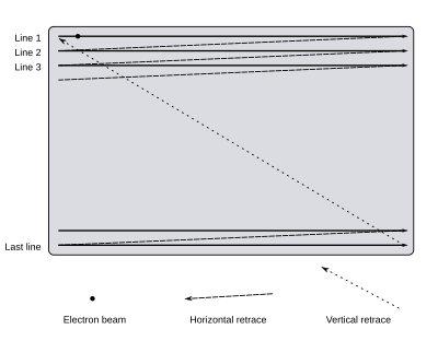
Raster scanning is performed from left-to-right and pinnacle-to-bottom. One time the screen has been scanned, the beam returns to the beginning of the kickoff line.

Close upward image of analog color screen
A cathode-ray tube (CRT) telly displays an image past scanning a axle of electrons across the screen in a pattern of horizontal lines known equally a raster. At the end of each line, the axle returns to the start of the side by side line; at the end of the last line, the axle returns to the beginning of the first line at the top of the screen. Every bit it passes each point, the intensity of the beam is varied, varying the luminance of that bespeak. A colour television receiver system is similar except at that place are 3 beams that browse together and an boosted point known as chrominance controls the color of the spot.
When analog tv was developed, no affordable technology for storing video signals existed; the luminance signal had to be generated and transmitted at the same time at which it is displayed on the CRT. Information technology was therefore essential to go along the raster scanning in the camera (or other device for producing the bespeak) in exact synchronization with the scanning in the television.
The physics of the CRT require that a finite fourth dimension interval be allowed for the spot to motion back to the get-go of the next line (horizontal retrace) or the start of the screen (vertical retrace). The timing of the luminance indicate must allow for this.
The human centre has a feature chosen phi phenomenon. Rapidly displaying successive scan images creates the illusion of smooth motion. Flickering of the prototype can be partially solved using a long persistence phosphor coating on the CRT so that successive images fade slowly. However, tiresome phosphor has the negative side-event of causing prototype smearing and blurring when in that location is rapid on-screen motion occurring.
The maximum frame rate depends on the bandwidth of the electronics and the manual system, and the number of horizontal scan lines in the image. A frame charge per unit of 25 or 30 hertz is a satisfactory compromise, while the process of interlacing two video fields of the movie per frame is used to build the image. This procedure doubles the apparent number of video frames per second and further reduces flicker and other defects in transmission.
Receiving signals [edit]
The television receiver organisation for each country volition specify a number of television channels inside the UHF or VHF frequency ranges. A channel actually consists of ii signals: the motion picture data is transmitted using amplitude modulation on one carrier frequency, and the audio is transmitted with frequency modulation at a frequency at a fixed kickoff (typically 4.5 to 6 MHz) from the picture signal.
The channel frequencies called stand for a compromise between allowing plenty bandwidth for video (and hence satisfactory movie resolution), and allowing plenty channels to be packed into the available frequency ring. In do a technique called vestigial sideband is used to reduce the aqueduct spacing, which would be nearly twice the video bandwidth if pure AM was used.
Signal reception is invariably washed via a superheterodyne receiver: the beginning stage is a tuner which selects a idiot box channel and frequency-shifts information technology to a fixed intermediate frequency (IF). The indicate amplifier performs amplification to the IF stages from the microvolt range to fractions of a volt.
[edit]
At this signal the IF signal consists of a video carrier signal at 1 frequency and the sound carrier at a fixed showtime in frequency. A demodulator recovers the video signal. Also at the output of the same demodulator is a new frequency modulated audio carrier at the offset frequency. In some sets fabricated before 1948, this was filtered out, and the sound IF of about 22 MHz was sent to an FM demodulator to recover the basic sound betoken. In newer sets, this new carrier at the offset frequency was allowed to remain as intercarrier sound, and it was sent to an FM demodulator to recover the bones sound point. I particular advantage of intercarrier sound is that when the front console fine tuning knob is adjusted, the audio carrier frequency does not alter with the tuning, but stays at the above-mentioned start frequency. Consequently, information technology is easier to tune the pic without losing the sound.
So the FM sound carrier is then demodulated, amplified, and used to drive a loudspeaker. Until the advent of the NICAM and MTS systems, television sound transmissions were monophonic.
Structure of a video bespeak [edit]
The video carrier is demodulated to give a composite video point[f] containing luminance, chrominance and synchronization signals.[5] The result is identical to the composite video format used by analog video devices such as VCRs or CCTV cameras. To ensure skillful linearity and thus fidelity, consistent with affordable manufacturing costs of transmitters and receivers, the video carrier is never modulated to the extent that it is shut off altogether. When intercarrier sound was introduced afterward in 1948, not completely shutting off the carrier had the side effect of allowing intercarrier audio to be economically implemented.

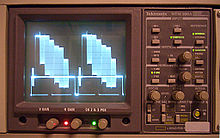
A waterfall display showing an 20ms long interlaced PAL frame with loftier FFT resolution
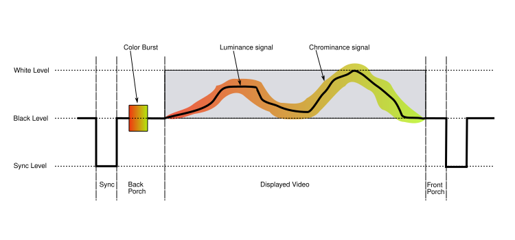
Each line of the displayed image is transmitted using a signal every bit shown higher up. The same bones format (with small-scale differences mainly related to timing and the encoding of color) is used for PAL, NTSC, and SECAM television systems. A monochrome signal is identical to a color one, with the exception that the elements shown in color in the diagram (the colour outburst, and the chrominance signal) are non present.
Portion of a PAL video signal. From left to right: end of a video browse line, back porch, horizontal sync pulse, forepart porch with color flare-up, and start of next line
The front porch is a brief (about one.5 microsecond) period inserted between the end of each transmitted line of picture and the leading edge of the adjacent line's sync pulse. Its purpose was to allow voltage levels to stabilise in older televisions, preventing interference betwixt picture lines. The front porch is the showtime component of the horizontal blanking interval which too contains the horizontal sync pulse and the back porch.[half-dozen] [seven] [8]
The back porch is the portion of each scan line between the cease (rising edge) of the horizontal sync pulse and the commencement of active video. It is used to restore the black level (300 mV) reference in analog video. In bespeak processing terms, it compensates for the fall time and settling time following the sync pulse.[6] [7]
In color television receiver systems such as PAL and NTSC, this period besides includes the colorburst signal. In the SECAM system, it contains the reference subcarrier for each consecutive color difference bespeak in order to fix the zero-color reference.
In some professional systems, particularly satellite links between locations, the digital sound is embedded inside the line sync pulses of the video signal, to relieve the cost of renting a 2d aqueduct. The name for this proprietary organisation is Sound-in-Syncs.
[edit]
The luminance component of a blended video signal varies between 0 V and approximately 0.7 5 above the blackness level. In the NTSC arrangement, there is a blanking signal level used during the front porch and dorsum porch, and a blackness point level 75 mV above it; in PAL and SECAM these are identical.
In a monochrome receiver, the luminance indicate is amplified to drive the control grid in the electron gun of the CRT. This changes the intensity of the electron beam and therefore the effulgence of the spot being scanned. Brightness and contrast controls determine the DC shift and distension, respectively.
[edit]

Color bar generator test point
A color signal conveys moving-picture show information for each of the crimson, light-green, and blueish components of an image. However, these are not simply transmitted as three separate signals, considering: such a point would non be uniform with monochrome receivers, an important consideration when color broadcasting was beginning introduced. Information technology would also occupy three times the bandwidth of existing television, requiring a decrease in the number of television set channels bachelor.
Instead, the RGB signals are converted into YUV form, where the Y point represents the luminance of the colors in the prototype. Because the rendering of colors in this way is the goal of both monochrome film and idiot box systems, the Y indicate is ideal for transmission as the luminance signal. This ensures a monochrome receiver will display a correct picture in blackness and white, where a given colour is reproduced by a shade of gray that correctly reflects how lite or dark the original color is.
The U and Five signals are "color difference" signals. The U betoken is the deviation between the B signal and the Y signal, also known as B minus Y (B-Y), and the V indicate is the deviation between the R signal and the Y signal, as well known equally R minus Y (R-Y). The U signal then represents how "purplish-blue" or its complementary color "yellowish-green" the colour is, and the Five bespeak how "purplish-cerise" or it's complementary "dark-green-cyan" it is. The reward of this scheme is that the U and V signals are zero when the motion picture has no color content. Since the man eye is more than sensitive to particular in luminance than in color, the U and V signals can be transmitted in a relatively lossy (specifically: bandwidth-limited) mode with acceptable results.
In the receiver, a single demodulator tin extract an additive combination of U plus V. An case is the X demodulator used in the X/Z demodulation system. In that aforementioned system, a 2d demodulator, the Z demodulator, likewise extracts an additive combination of U plus V, but in a dissimilar ratio. The Ten and Z colour deviation signals are further matrixed into 3 color difference signals, (R-Y), (B-Y), and (G-Y). The combinations of usually two, but sometimes three demodulators were:
- (I) / (Q), (as used in the 1954 RCA CTC-2 and the 1985 RCA "Colortrak" series, and the 1954 Arvin, and some professional color monitors in the 1990s),
- (R-Y) / (Q), as used in the 1955 RCA 21-inch colour receiver,
- (R-Y) / (B-Y), used in the first color receiver on the market (Westinghouse, non RCA),
- (R-Y) / (G-Y), (as used in the RCA Victor CTC-4 chassis),
- (R-Y) / (B-Y) / (G-Y),
- (X) / (Z), as used in many receivers of the belatedly '50s and throughout the '60s.
In the end, farther matrixing of the above colour-deviation signals c through f yielded the 3 color-difference signals, (R-Y), (B-Y), and (G-Y).
The R, Chiliad, B signals in the receiver needed for the display device (CRT, Plasma brandish, or LCD display) are electronically derived by matrixing every bit follows: R is the additive combination of (R-Y) with Y, Grand is the additive combination of (Chiliad-Y) with Y, and B is the additive combination of (B-Y) with Y. All of this is accomplished electronically. It can be seen that in the combining process, the low-resolution portion of the Y signals abolish out, leaving R, G, and B signals able to render a low-resolution image in full color. However, the college resolution portions of the Y signals practise not cancel out, and and then are every bit nowadays in R, G, and B, producing the higher definition (higher resolution) image detail in monochrome, although it appears to the human being eye as a full-color and full resolution picture.
Color signals mixed with the video signal (ii horizontal lines in sequence)
In the NTSC and PAL color systems, U and V are transmitted by using quadrature amplitude modulation of a subcarrier. This kind of modulation applies two independent signals to 1 subcarrier, with the thought that both signals will be recovered independently at the receiving terminate. Before transmission, the subcarrier itself is removed from the active (visible) portion of the video, and moved, in the form of a flare-up, to the horizontal blanking portion, which is not direct visible on the screen. (More well-nigh the flare-up below.)
For NTSC, the subcarrier is a three.58 MHz sine wave. For the PAL system it is a 4.43 MHz sine wave. Later the above-mentioned quadrature amplitude modulation of the subcarrier, subcarrier sidebands are produced, and the subcarrier itself is filtered out of the visible portion of the video, since it is the subcarrier sidebands that acquit all of the U and 5 information, and the subcarrier itself carries no information.
The resulting subcarrier sidebands are also known as "chroma" or "chrominance". Physically, this chrominance signal is a 3.58 MHz (NTSC) or iv.43 MHz (PAL) sine wave which, in response to changing U and V values, changes phase as compared to the subcarrier, and likewise changes amplitude.
As information technology turns out, the chroma amplitude (when considered together with the Y signal) represents the estimate saturation of a colour, and the chroma stage against the subcarrier as reference approximately represents the hue of the color. For particular test colors establish in the test color bar design, exact amplitudes and phases are sometimes defined for test and troubleshooting purposes only.
Although in response to changing U and V values, the chroma sinewave changes phase with respect to the subcarrier, it'southward not correct to say that the subcarrier is simply "phase modulated". That is because a unmarried sine wave U test signal with QAM produces simply i pair of sidebands, whereas real phase modulation under the same test conditions would produce multiple sets of sidebands occupying a more frequency spectrum.
In NTSC, the chrominance sine wave has the same average frequency as the subcarrier frequency. But a spectrum analyzer instrument shows that, for transmitted chrominance, the frequency component at the subcarrier frequency is really zero free energy, verifying that the subcarrier was indeed removed before transmission.
These sideband frequencies are within the luminance signal band, which is why they are called "subcarrier" sidebands instead of simply "carrier" sidebands. Their exact frequencies were called such that (for NTSC), they are midway between ii harmonics of the frame repetition rate, thus ensuring that the majority of the power of the luminance point does not overlap with the power of the chrominance signal.
In the British PAL (D) organization, the actual chrominance centre frequency, with equal lower and upper sidebands, is 4.43361875 MHz, a straight multiple of the scan charge per unit frequency. This frequency was chosen to minimize the chrominance beat interference pattern that would be visible in areas of high color saturation in the transmitted picture show.
At certain times, the chrominance signal represents only the U signal, and 70 nanoseconds (NTSC) later, the chrominance indicate represents only the V bespeak. (This is the nature of the quadrature amplitude modulation process that created the chrominance bespeak.) Almost 70 nanoseconds later still, -U, and another seventy nanoseconds, -5.
So to extract U, a synchronous demodulator is utilized, which uses the subcarrier to briefly gate (sample) the chroma every 280 nanoseconds, so that the output is merely a train of discrete pulses, each having an amplitude that is the same as the original U point at the corresponding time. In event, these pulses are discrete-fourth dimension analog samples of the U bespeak. The pulses are and then low-laissez passer filtered then that the original analog continuous-time U signal is recovered. For V, a 90-caste shifted subcarrier briefly gates the blush signal every 280 nanoseconds, and the residue of the process is identical to that used for the U indicate.
Gating at any other time than those times mentioned above volition yield an additive mixture of any two of U, Five, -U, or -V. One of these "off-axis" (that is, of the U and 5 axis) gating methods is called I/Q demodulation. Another much more popular "off-axis" scheme was the Ten/Z demodulation system. Further matrixing recovered the original U and Five signals. This scheme was actually the most popular demodulator scheme throughout the 60s.
The above process uses the subcarrier. Only as previously mentioned, it was deleted before transmission, and simply the chroma is transmitted. Therefore, the receiver must reconstitute the subcarrier. For this purpose, a short flare-up of the subcarrier, known as the color burst, is transmitted during the dorsum porch (re-trace blanking period) of each browse line. A subcarrier oscillator in the receiver locks onto this signal (run into phase-locked loop) to achieve a phase reference, resulting in the oscillator producing the reconstituted subcarrier.
(A second use of the burst in more expensive or newer receiver models is a reference to an AGC organization to compensate for blush gain imperfections in reception.)
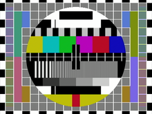
Test card showing "Hanover bars" (color banding phase effect) in Pal Southward (simple) indicate style of manual.
NTSC uses this process unmodified. Unfortunately, this oft results in poor color reproduction due to phase errors in the received signal, caused sometimes past multipath, simply more often than not by poor implementation at the studio end. With the appearance of solid-state receivers, cablevision TV, and digital studio equipment for conversion to an over-the-air analog indicate, these NTSC issues have been largely stock-still, leaving operator fault at the studio end as the sole colour rendition weakness of the NTSC organisation. In any example, the PAL D (delay) organisation mostly corrects these kinds of errors past reversing the phase of the bespeak on each successive line, and averaging the results over pairs of lines. This process is achieved past the use of a 1H (where H = horizontal browse frequency) duration filibuster line. (A typical circuit used with this device converts the low-frequency color signal to ultrasound and back again). Phase shift errors between successive lines are therefore canceled out and the wanted signal aamplitude is increased when the 2 in-stage (coincident) signals are re-combined.
NTSC is more spectrum efficient than PAL, giving more picture detail for a given bandwidth. This is because sophisticated comb filters in receivers are more effective with NTSC's 4 field color phase cadence compared to PAL'due south viii field cadency. However, in the end, the larger channel width of about PAL systems in Europe nonetheless requite their PAL systems the edge in transmitting more picture particular.
In the SECAM television arrangement, U and V are transmitted on alternating lines, using simple frequency modulation of ii different color subcarriers.
In some analog color CRT displays, starting in 1956, the brightness control betoken (luminance) is fed to the cathode connections of the electron guns, and the color divergence signals (chrominance signals) are fed to the control grids connections. This simple CRT matrix mixing technique was replaced in later solid state designs of indicate processing with the original matrixing method used in the 1954 and 1955 color Television receiver receivers.
Synchronization [edit]
Synchronizing pulses added to the video signal at the end of every scan line and video frame ensure that the sweep oscillators in the receiver remain locked in step with the transmitted betoken so that the image can be reconstructed on the receiver screen.[half-dozen] [seven] [9]
A sync separator circuit detects the sync voltage levels and sorts the pulses into horizontal and vertical sync.
Horizontal synchronization [edit]
The horizontal synchronization pulse (horizontal sync, or HSync), separates the browse lines. The horizontal sync indicate is a single short pulse which indicates the starting time of every line. The remainder of the scan line follows, with the signal ranging from 0.3 V (black) to 1 5 (white), until the next horizontal or vertical synchronization pulse.
The format of the horizontal sync pulse varies. In the 525-line NTSC arrangement it is a 4.85 μs-long pulse at 0 Five. In the 625-line PAL system the pulse is 4.7 μs synchronization pulse at 0 V . This is lower than the amplitude of any video signal (blacker than blackness) and so it can be detected past the level-sensitive "sync stripper" circuit of the receiver.
Vertical synchronization [edit]
Vertical synchronization (besides chosen vertical sync or VSync) separates the video fields. In PAL and NTSC, the vertical sync pulse occurs within the vertical blanking interval. The vertical sync pulses are made by prolonging the length of HSYNC pulses through almost the entire length of the scan line.
The vertical sync betoken is a series of much longer pulses, indicating the kickoff of a new field. The sync pulses occupy the whole line interval of a number of lines at the beginning and terminate of a scan; no picture information is transmitted during vertical retrace. The pulse sequence is designed to allow horizontal sync to continue during vertical retrace; information technology also indicates whether each field represents even or odd lines in interlaced systems (depending on whether information technology begins at the start of a horizontal line, or midway through).
The format of such a signal in 525-line NTSC is:
- pre-equalizing pulses (6 to start scanning odd lines, 5 to beginning scanning even lines)
- long-sync pulses (5 pulses)
- post-equalizing pulses (5 to starting time scanning odd lines, 4 to start scanning even lines)
Each pre- or post- equalizing pulse consists in half a scan line of black signal: two μs at 0 V, followed by 30 μs at 0.3 Five.
Each long sync pulse consists of an equalizing pulse with timings inverted: 30 μs at 0 V, followed by two μs at 0.3 V.
In video production and calculator graphics, changes to the image are often kept in stride with the vertical synchronization pulse to avoid visible discontinuity of the paradigm. Since the frame buffer of a computer graphics display imitates the dynamics of a cathode-ray brandish, if it is updated with a new image while the image is existence transmitted to the display, the display shows a hodgepodge of both frames, producing a page tearing artifact partway downward the image.
Vertical synchronization eliminates this by timing frame buffer fills to coincide with the vertical blanking interval, thus ensuring that but whole frames are seen on-screen. Software such as video games and computer-aided design (CAD) packages often permit vertical synchronization as an option, considering it delays the image update until the vertical blanking interval. This produces a small penalty in latency considering the program has to wait until the video controller has finished transmitting the image to the display before standing. Triple buffering reduces this latency significantly.
Two-timing intervals are defined – the front end porch betwixt the stop of the displayed video and the start of the sync pulse, and the dorsum porch after the sync pulse and before the displayed video. These and the sync pulse itself are called the horizontal blanking (or retrace) interval and stand for the time that the electron beam in the CRT is returning to the start of the next display line.
Horizontal and vertical concur [edit]
Analog tv receivers and composite monitors often provide manual controls to adjust horizontal and vertical timing.
The sweep (or deflection) oscillators were designed to run without a signal from the idiot box station (or VCR, estimator, or other blended video source). This provides a bare canvas, similar to today's "Bank check SIGNAL CABLE" messages on monitors: it allows the tv receiver to display a raster to confirm the bones operation of the set up'due south most fundamental circuits, and to allow an prototype to exist presented during antenna placement. With sufficient signal strength, the receiver'southward sync separator circuit would dissever timebase pulses from the incoming video and use them to reset the horizontal and vertical oscillators at the advisable fourth dimension to synchronize with the point from the station.
The free-running oscillation of the horizontal circuit is particularly critical, as the horizontal deflection circuits typically ability the flyback transformer (which provides acceleration potential for the CRT) likewise equally the filaments for the high voltage rectifier tube and sometimes the filament(s) of the CRT itself. Without the performance of the horizontal oscillator and output stages, for virtually every analog television set since the 1940s, there will exist absolutely no illumination of the CRT'south confront.
The lack of precision timing components in early boob tube receivers meant that the timebase circuits occasionally needed manual aligning. If their free-run frequencies were too far from the actual line and field rates, the circuits would not exist able to follow the incoming sync signals. Loss of horizontal synchronization usually resulted in an unwatchable picture; loss of vertical synchronization would produce an image rolling up or down the screen.
The aligning took the form of horizontal concord and vertical concur controls, usually on the front panel forth with other common controls. These adjusted the free-run frequencies of the corresponding timebase oscillators.
Properly working, adjusting a horizontal or vertical hold should crusade the picture to almost "snap" into place on the screen; this is called sync lock. A slowly rolling vertical movie demonstrates that the vertical oscillator is about synchronized with the goggle box station but is not locking to it, oftentimes due to a weak betoken or a failure in the sync separator phase not resetting the oscillator. Sometimes, the black interval bar volition almost finish at the correct place, again indicating a fault in sync separation is not properly resetting the vertical oscillator.
Horizontal sync errors crusade the prototype to be torn diagonally and repeated across the screen as if it were wrapped around a spiral or a hairdresser's pole; the greater the fault, the more "copies" of the image will be seen at one time wrapped around the barber pole. Given the importance of the horizontal sync circuit as a power supply to many subcircuits in the receiver, they may brainstorm to malfunction as well; and horizontal output components that were designed to work together in a resonant circuit may become damaged.
In the earliest electronic television receivers (1930s-1950s), the time base for the sweep oscillators was generally derived from RC circuits based on carbon resistors and paper capacitors. After turning on the receiver, the vacuum tubes in the gear up would warm up and the oscillators would begin to run, allowing a watchable picture. Resistors were generally elementary pieces of carbon inside a Bakelite enclosure, and the capacitors were usually alternating layers of paper and aluminum foil inside cardboard tubes sealed with bee'due south wax. Wet ingress (from ambient air humidity) as well as thermal instability of these components affected their electrical values. As the heat from the tubes and the electrical currents passing through the RC circuits warmed them up, the electrical properties of the RC timebase would shift, causing the oscillators to drift in frequency to a point that they could no longer exist synchronized with the received pulses coming from the Idiot box station via the sync separator circuit, causing violent (horizontal) or rolling (vertical).
Hermetically-sealed passive components and cooler-running semiconductors equally agile components gradually improved reliability to the point where the horizontal hold was moved to the rear of the fix first, and the vertical hold control (due to the longer flow in the RC constant) persisted as a front panel control well into the 1970s as the consistency of larger-value capacitors increased.
By the early 1980s the efficacy of the synchronization circuits, plus the inherent stability of the sets' oscillators, had been improved to the signal where these controls were no longer necessary. Integrated Circuits which eliminated the horizontal hold control were starting to appear as early every bit 1969.[10]
The final generations of analog television receivers (almost Television receiver sets with internal on-screen displays to adjust brightness, color, tint, contrast) used "Television receiver-ready-on-a-chip" designs where the receiver's timebases were divided down from crystal oscillators, usually based on the 3.58 MHz NTSC colorburst reference. PAL and SECAM receivers were similar though operating at different frequencies. With these sets, adjustment of the complimentary-running frequency of either sweep oscillator was either physically incommunicable (being derived inside the integrated circuit) or peradventure through a hidden service mode typically offer only NTSC/PAL frequency switching, accessible through the On-Screen Display's menu system.
Horizontal and Vertical Hold controls were rarely used in CRT-based computer monitors, as the quality and consistency of components were quite high by the advent of the computer age, but might be found on some composite monitors used with the 1970s-1980s home or personal computers.
There is no equivalent in modern television systems.
Other technical information [edit]
Components of a boob tube system [edit]
A typical analog monochrome telly is based around the cake diagram shown beneath:
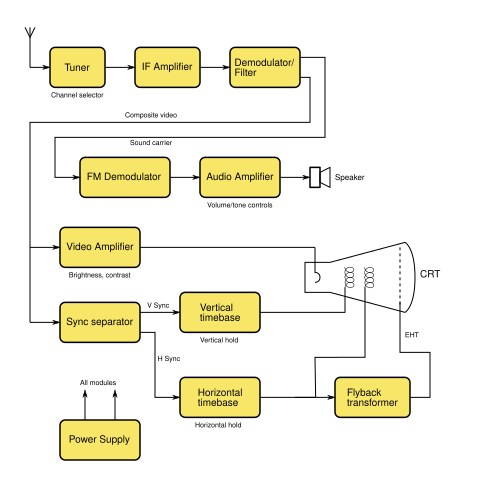
The tuner is the object which "plucks" the tv set signals out of the air, with the assist of an antenna. In that location are ii types of tuners in analog television, VHF and UHF tuners. The VHF tuner selects the VHF television set frequency. This consists of a 4 MHz video bandwidth and a 2 MHz audio bandwidth. Information technology then amplifies the signal and converts it to a 45.75 MHz Intermediate Frequency (IF) amplitude-modulated picture and a 41.25 MHz IF frequency-modulated audio carrier.
The IF amplifiers are centered at 44 MHz for optimal frequency transference of the audio and frequency carriers. What centers this frequency is the IF transformer. They are designed for a sure amount of bandwidth to comprehend the audio and video. It depends on the number of stages (the amplifier between the transformers). Most of the early television set sets (1939–45) used 4 stages with specially designed video amplifier tubes (the blazon 1852/6AC7). In 1946 the RCA presented a new innovation in television receiver; the RCA 630TS. Instead of using the 1852 octal tube, it uses the 6AG5 vii-pin miniature tube. It all the same had 4 stages, simply information technology was 1/2 the size. Presently all of the manufactures followed RCA and designed meliorate IF stages. They developed college distension tubes, and lower stage counts with more than amplification. When the tube era came to an stop in the mid-70s, they had shrunk the IF stages down to 1-ii (depending on the set) and with the same distension equally the iv stage, 1852 tube sets. Similar radio, television has Automatic Proceeds Control (AGC). This controls the gain of the IF amplifier stages and the tuner. More of this will be discussed below.
The video amp and output amplifier consist of a low linear pentode or a high powered transistor. The video amp and output phase dissever the 45.75 MHz from the 41.25 MHz. Information technology just uses a diode to discover the video signal. But the frequency-modulated audio is nonetheless in the video. Since the diode only detects AM signals, the FM audio indicate is still in the video in the class of a 4.5 MHz signal. In that location are 2 ways to attach this problem, and both of them work. We tin can detect the signal before it enters into the video amplifier, or do it later on the sound amplifier. Many tv set sets (1946 to belatedly 1960s) used the afterwards video amplification method, but of form, at that place is the occasional exception. Many of the later on set late (1960s-now) use the before-the-video amplifier way. In some of the early on idiot box sets (1939–45) used its own separate tuner, so in that location was no need for a detection stage next to the amplifier. After the video detector, the video is amplified and sent to the sync separator and then to the picture tube.
At this point, we will now look at the audio section. The means of detection of the sound signal is by a iv.v MHz traps curl/transformer. After that, it then goes to a 4.5 MHz amplifier. This amplifier prepares the betoken for the 4.5Mhz detector. Information technology then goes through a 4.5 MHz IF transformer to the detector. In television, there are 2 ways of detecting FM signals. 1 way is by the ratio detector. This is simple just very hard to align. The next is a relatively simple detector. This is the quadrature detector. It was invented in 1954. The first tube designed for this purpose was the 6BN6 type. It is like shooting fish in a barrel to marshal and simple in circuitry. It was such a good blueprint that information technology is nevertheless being used today in the Integrated circuit class. After the detector, it goes to the audio amplifier.
The next part is the sync separator/clipper. This also does more than than what is in its name. It also forms the AGC voltage, as previously stated. This sync separator turns the video into a signal that the horizontal and vertical oscillators tin can employ to keep in sync with the video.
The horizontal and vertical oscillators grade the raster on the CRT. They are kept in sync by the sync separator. In that location are many ways to create these oscillators. The commencement one is the primeval of its kind is the thyratron oscillator. Although information technology is known to drift, it makes a perfect sawtooth wave. This sawtooth moving ridge is then good that no linearity command is needed. This oscillator was for the electrostatic deflection CRTs. It found some purpose for the electromagnetically deflected CRTs. The adjacent oscillator is the blocking oscillator. It uses a transformer to create a sawtooth wave. This was just used for a cursory time menstruum and never was very popular afterwards the starting time. The adjacent oscillator is the multivibrator. This oscillator was probably the nigh successful. It needed more adjustment than the other oscillators, but information technology is very simple and effective. This oscillator was so pop that it was used from the early 1950s until today.
The oscillator amplifier is sorted into ii categories. The vertical amplifier directly drives the yoke. There is not much to this. It is like to an audio amplifier. The horizontal oscillator is a dissimilar state of affairs. The oscillator must supply the high voltage and the yoke power. This requires a high power flyback transformer, and a loftier powered tube or transistor. This is a problematic section for CRT televisions because it has to handle high power.
Sync separator [edit]

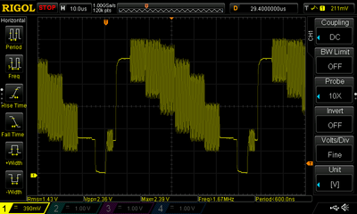
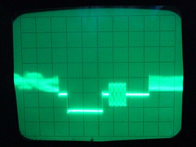
Portion of a PAL videosignal. From left to right: end of a video line, front porch, horizontal sync pulse, dorsum porch with color burst, and start of next line
Beginning of the frame, showing several browse lines; the concluding part of the vertical sync pulse is at the left

PAL video point frames. Left to right: frame with scan lines (overlapping together, horizontal sync pulses evidence as the doubled directly horizontal lines), vertical blanking interval with vertical sync (shows as brightness increase of the bottom part of the betoken in almost the leftmost part of the vertical blanking interval), entire frame, some other VBI with VSYNC, outset of the third frame

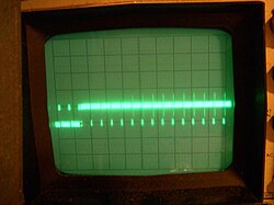
Analyzing a PAL bespeak and decoding the 20ms frame and 64µs lines
Image synchronization is accomplished by transmitting negative-going pulses; in a composite video bespeak of 1-volt amplitude, these are approximately 0.3 V below the "black level". The horizontal sync signal is a single brusque pulse which indicates the start of every line. Two-timing intervals are divers – the front porch between the end of the displayed video and the get-go of the sync pulse, and the dorsum porch afterward the sync pulse and before the displayed video. These and the sync pulse itself are called the horizontal blanking (or retrace) interval and represent the time that the electron beam in the CRT is returning to the start of the next display line.
The vertical sync signal is a series of much longer pulses, indicating the beginning of a new field. The sync pulses occupy the whole of line interval of a number of lines at the offset and stop of a scan; no picture information is transmitted during vertical retrace. The pulse sequence is designed to let horizontal sync to continue during vertical retrace; information technology also indicates whether each field represents even or odd lines in interlaced systems (depending on whether information technology begins at the kickoff of a horizontal line, or midway through).
In the television receiver, a sync separator excursion detects the sync voltage levels and sorts the pulses into horizontal and vertical sync.
Loss of horizontal synchronization usually resulted in an unwatchable pic; loss of vertical synchronization would produce an prototype rolling up or down the screen.
Counting sync pulses, a video line selector picks a selected line from a Television set point, used for teletext, on-screen displays, station identification logos as well equally in the industry when cameras were used as a sensor.
Timebase circuits [edit]
In an analog receiver with a CRT display sync pulses are fed to horizontal and vertical timebase circuits (commonly chosen "sweep circuits" in the Usa), each consisting of an oscillator and an amplifier. These generate modified sawtooth and parabola current waveforms to browse the electron beam in a linear way. The waveform shapes are necessary to make up for the distance variations from the electron beam source and the screen surface. The oscillators are designed to free-run at frequencies very close to the field and line rates, merely the sync pulses cause them to reset at the beginning of each browse line or field, resulting in the necessary synchronization of the beam sweep with the originating point. The output waveforms from the timebase amplifiers are fed to the horizontal and vertical deflection coils wrapped around the CRT tube. These coils produce magnetic fields proportional to the irresolute current, and these deflect the electron axle across the screen.
In the 1950s, the power for these circuits was derived directly from the mains supply. A simple circuit consisted of a series voltage dropper resistance and a rectifier valve (tube) or semiconductor diode. This avoided the cost of a big high voltage mains supply (50 or 60 Hz) transformer. This type of circuit was used for the thermionic valve (vacuum tube) engineering. It was inefficient and produced a lot of heat which led to premature failures in the circuitry. Although failure was common, it was hands repairable.
In the 1960s, semiconductor technology was introduced into timebase circuits. During the late 1960s in the Great britain, synchronous (with the scan line charge per unit) power generation was introduced into solid state receiver designs.[11] These had very circuitous circuits in which faults were difficult to trace, just had very efficient apply of power.
In the early 1970s Air conditioning mains (50 or 60 Hz), and line timebase (fifteen,625 Hz), thyristor based switching circuits were introduced. In the UK use of the simple (l Hz) types of ability, circuits were discontinued. The reason for pattern changes arose from the electricity supply contamination problems arising from EMI,[12] and supply loading issues due to energy existence taken from but the positive half wheel of the mains supply waveform.[13]
CRT flyback power supply [edit]
Near of the receiver's circuitry (at least in transistor- or IC-based designs) operates from a comparatively depression-voltage DC power supply. However, the anode connectedness for a cathode-ray tube requires a very high voltage (typically ten–30 kV) for correct operation.
This voltage is not directly produced by the primary ability supply circuitry; instead, the receiver makes use of the circuitry used for horizontal scanning. Straight current (DC), is switched through the line output transformer, and alternating current (Air-conditioning) is induced into the scan coils. At the finish of each horizontal scan line the magnetic field, which has built upwardly in both transformer and browse coils by the electric current, is a source of latent electromagnetic free energy. This stored collapsing magnetic field energy can be captured. The contrary menses, short duration, (about 10% of the line scan time) current from both the line output transformer and the horizontal scan scroll is discharged again into the chief winding of the flyback transformer by the apply of a rectifier which blocks this negative reverse emf. A small-scale value capacitor is connected beyond the scan switching device. This tunes the circuit inductances to resonate at a much higher frequency. This slows down (lengthens) the flyback time from the extremely rapid decay rate that would result if they were electrically isolated during this short period. One of the secondary windings on the flyback transformer then feeds this brief high voltage pulse to a Cockcroft–Walton generator blueprint voltage multiplier. This produces the required EHT supply. A flyback converter is a power supply circuit operating on similar principles.
A typical modern blueprint incorporates the flyback transformer and rectifier circuitry into a single unit with a convict output atomic number 82, (known as a diode split line output transformer or an Integrated High Voltage Transformer (IHVT)),[fourteen] then that all loftier-voltage parts are enclosed. Earlier designs used a separate line output transformer and a well-insulated high voltage multiplier unit. The high frequency (15 kHz or so) of the horizontal scanning allows reasonably small components to be used.
Transition to digital [edit]
In many countries, over-the-air broadcast television of analog audio and analog video signals has been discontinued, to allow the re-use of the boob tube broadcast radio spectrum for other services such as datacasting and subchannels.
The beginning land to make a wholesale switch to digital over-the-air (terrestrial goggle box) broadcasting was Luxembourg in 2006, followed later in 2006 by the Netherlands; in 2007 by Finland, Andorra, Sweden and Switzerland; in 2008 by Kingdom of belgium (Flanders) and Germany; in 2009 past the United States (high ability stations), southern Canada, the Isle of mann, Norway, and Denmark. In 2010, Belgium (Wallonia), Spain, Wales, Latvia, Estonia, the Channel Islands, San Marino, Croatia, and Slovenia; in 2011 Israel, Republic of austria, Monaco, Cyprus, Nihon (excluding Miyagi, Iwate, and Fukushima prefectures), Malta and France; in 2012 the Czech republic, Arab World, Taiwan, Portugal, Japan (including Miyagi, Iwate, and Fukushima prefectures), Serbia, Italy, Canada, Mauritius, the United Kingdom, the Ireland, Lithuania, Slovakia, Gibraltar, and Due south Korea; in 2013, the Republic of Macedonia, Poland, Bulgaria, Hungary, Australia, and New Zealand, completed the transition. The Great britain made the transition to digital television betwixt 2008 and 2012, with the exception of Whitehaven, which fabricated the switch over in 2007. The first digital TV-just surface area in the Great britain was Ferryside in Carmarthenshire.[ citation needed ]
The Digital idiot box transition in the U.s.a. for high-powered transmission was completed on 12 June 2009, the date that the Federal Communications Commission (FCC) set. Well-nigh two 1000000 households could no longer scout idiot box considering they had not prepared for the transition. The switchover had been delayed by the DTV Delay Act.[fifteen] While the majority of the viewers of over-the-air broadcast goggle box in the U.S. watch full-power stations (which number nearly 1800), in that location are three other categories of television receiver stations in the U.Due south.: low-power broadcasting stations, form A stations, and television receiver translator stations. They were given later deadlines. In dissemination, any happens in the United States also influences southern Canada and northern Mexico because those areas are covered past television stations in the U.S.
In Japan, the switch to digital began in northeastern Ishikawa Prefecture on 24 July 2010 and ended in 43 of the country's 47 prefectures (including the rest of Ishikawa) on 24 July 2011, only in Fukushima, Iwate, and Miyagi prefectures, the conversion was delayed to 31 March 2012, due to complications from the 2011 Tōhoku earthquake and tsunami and its related nuclear accidents.
In Canada, virtually of the larger cities turned off analog broadcasts on 31 Baronial 2011.[16]
China is scheduled to end analog broadcasting betwixt 2015 and 2018.[ citation needed ]
Brazil switched to digital television on 2 December 2007 in its major cities. Information technology is now estimated that Brazil will end analog broadcasting in 2023.[17]
In Malaysia, the Malaysian Communications & Multimedia Commission (MCMC) advertised for tender bids to exist submitted in the third quarter of 2009 for the 470 through 742 MHz UHF allocation, to enable Malaysia's broadcast system to move into DTV. The new broadcast ring allocation would upshot in Malaysia's having to build an infrastructure for all broadcasters, using a single digital terrestrial transmission/television broadcast (DTTB) channel.[ citation needed ] Large portions of Malaysia are covered by boob tube broadcasts from Singapore, Thailand, Brunei, and Indonesia (from Borneo and Batam). Starting from one Nov 2019, all regions in Malaysia were no longer using the analog system later the states of Sabah and Sarawak finally turned information technology off on 31 October 2019.[xviii]
In Singapore, digital idiot box under DVB-T2 began on 16 December 2013. The switchover was delayed many times until analog Telly was switched off at midnight on 2 Jan 2019.[19]
In the Philippines, the National Telecommunications Commission required all broadcasting companies to finish analog broadcasting on 31 Dec 2015 at 11:59 p.m. Due to filibuster of the release of the implementing rules and regulations for digital television broadcast, the target date was moved to 2020. Total digital broadcast is expected in 2021 and all of the analog TV services should be shut down past the finish of 2023.[ commendation needed ]
In the Russian Federation, the Russian Television set and Radio Broadcasting Network (RTRS) disabled analog dissemination of federal channels in five stages, shutting down broadcasting in multiple federal subjects at each stage. The starting time region to have analog broadcasting disabled was Tver Oblast on iii December 2018, and the switchover was completed on xiv Oct 2019.[20] During the transition, DVB-T2 receivers and budgetary compensations for purchasing of terrestrial or satellite digital TV reception equipment were provided to disabled people, Earth State of war II veterans, certain categories of retirees and households with income per member beneath living wage.[21]
See also [edit]
- Amateur television
- Colour outburst
- Narrow-bandwidth tv
- Overscan
- Slow-scan television set
- Terrestrial tv
- Telly transmitter
- Vertical blanking interval
- Field (video)
- Video frame
- Glossary of video terms
Notes [edit]
- ^ Many of these countries have transitioned or are transitioning to digital
- ^ Discontinued in 2012, when Nippon transitioned to digital (ISDB)
- ^ Discontinued in 2012, when UK transitioned to digital (DVB-T)
- ^ Discontinued in 2011, when France transitioned to digital (DVB-T)
- ^ Many of these transitioned or transitioning to DVB-T every bit digital television standards
- ^ The RF signal modulation is inverted compared to the conventional AM – the minimum video signal level corresponds to maximum carrier amplitude, and vice versa.
References [edit]
- ^ "Goggle box Technical Operation Code" (PDF). Ofcom – part of Communications. Dec 2006. Archived (PDF) from the original on 4 July 2011. Retrieved 24 November 2010.
- ^ "Idiot box Technology PAL". Publication date unknown. Thinkbox. Archived from the original on v Dec 2010. Retrieved 24 November 2010.
- ^ "Color Telly History". Publication date unknown. Nearly.com. Retrieved 24 November 2010.
- ^ "Color subcarrier frequency and Television receiver Standards/TV Systems". Publication dates 2002, 2003, 2004, 2005 last updated 2005/12/15. Paradiso Design. Retrieved 24 Nov 2010.
- ^ "Pal systems – Goggle box measurements" (PDF). Tektronics Incorporated. September 1999. Archived from the original (PDF) on 18 July 2011. Retrieved 25 Nov 2010.
- ^ a b c Gupta, R. Grand. (2006). Television Engineering and Video Systems. Tata McGraw-Colina. p. 62. ISBN0-07-058596-2.
- ^ a b c Pemberton, Alan (30 November 2008). "World Analogue Television receiver Standards and Waveforms". Pembers' Ponderings. Sheffield, England. Archived from the original on 20 February 2008. Retrieved 25 September 2010.
- ^ "Basics of Analog Video". www.maximintegrated.com. Maxim. Retrieved 21 May 2021.
- ^ Wharton, W.; Douglas Howorth (1971). Principles of Television Reception (illustrated ed.). Pitman Publishing. ISBN0-273-36103-1. OCLC 16244216.
- ^ Mills, Thomas. "A five function IC for television receivers". ResearchGate. IEEE. Retrieved 11 May 2019.
- ^ "TACKLING THE Ability SUPPLY". Publication appointment – unknown. Old Tellys.co.uk. Archived from the original on three March 2012. Retrieved 24 Nov 2010.
- ^ "An Investigation into the EMC Emissions From Switched Mode Power Supplies and Similar Switched Electronic Load Controllers Operating at Various Loading Conditions – p. 2, line 3" (PDF). Publication date – January 2001. York EMC.co.uk. Archived (PDF) from the original on 15 March 2012. Retrieved 24 Nov 2010.
- ^ "Review of Main Frequency Control Requirements on the GB Power System Against a Background of Increase in Renewable Generation – Impact of railway electrification systems on other electric systems and civil infrastructures inside and outside the railway environment.-section 3.two, p. fifteen" (PDF). October 2006. Bura.Brunel.air conditioning.uk. Archived (PDF) from the original on 15 March 2012. Retrieved 24 November 2010.
- ^ "Technical note 77 – Diode Split for Eastward.H.T. generation" (PDF). Publication date – 1976. Mullard. Archived from the original (PDF) on 21 July 2011. Retrieved 24 November 2010.
- ^ Stephanie Condon (26 January 2009). "Senate OKs delay of digital idiot box transition". CNET News. Archived from the original on 25 October 2012. Retrieved xiv June 2009.
- ^ "Archived copy". Archived from the original on 11 April 2009. Retrieved 5 May 2009.
{{cite web}}: CS1 maint: archived re-create as title (link) - ^ "Turning analog point off, new step in transition to digital". agenciadenoticias.ibge.gov.br . Retrieved 20 April 2020.
- ^ "Malaysia to turn off analogue TV completely on 31 October". 25 September 2019.
- ^ "Singapore pulls the plug on analogue TV transmission | Broadcast | News | Rapid Boob tube News".
- ^ "When analog TV channels volition be turned off". Russian Tv set and Radio Broadcasting Network . Retrieved fourteen October 2019.
- ^ Plotnikova, Elena (17 Feb 2019). "Bounty for digital TV. How to get 2000 rubles for buying a digital TV receiver". Argumenty i Fakty. Retrieved 14 Oct 2019.
External links [edit]
| | Look upward analog in Wiktionary, the free dictionary. |
- Video indicate measurement and generation
- Television synchronisation
- Video circulate standard frequencies and country listings
- EDN magazine describing blueprint of a 1958 transistorised tv set receiver
- Designing the color tv set signal in the early 1950s as described by two engineers working direct with the NTSC
Source: https://en.wikipedia.org/wiki/Analog_television
0 Response to "what does a loose connection do to hum modulation in catv"
Postar um comentário